Index
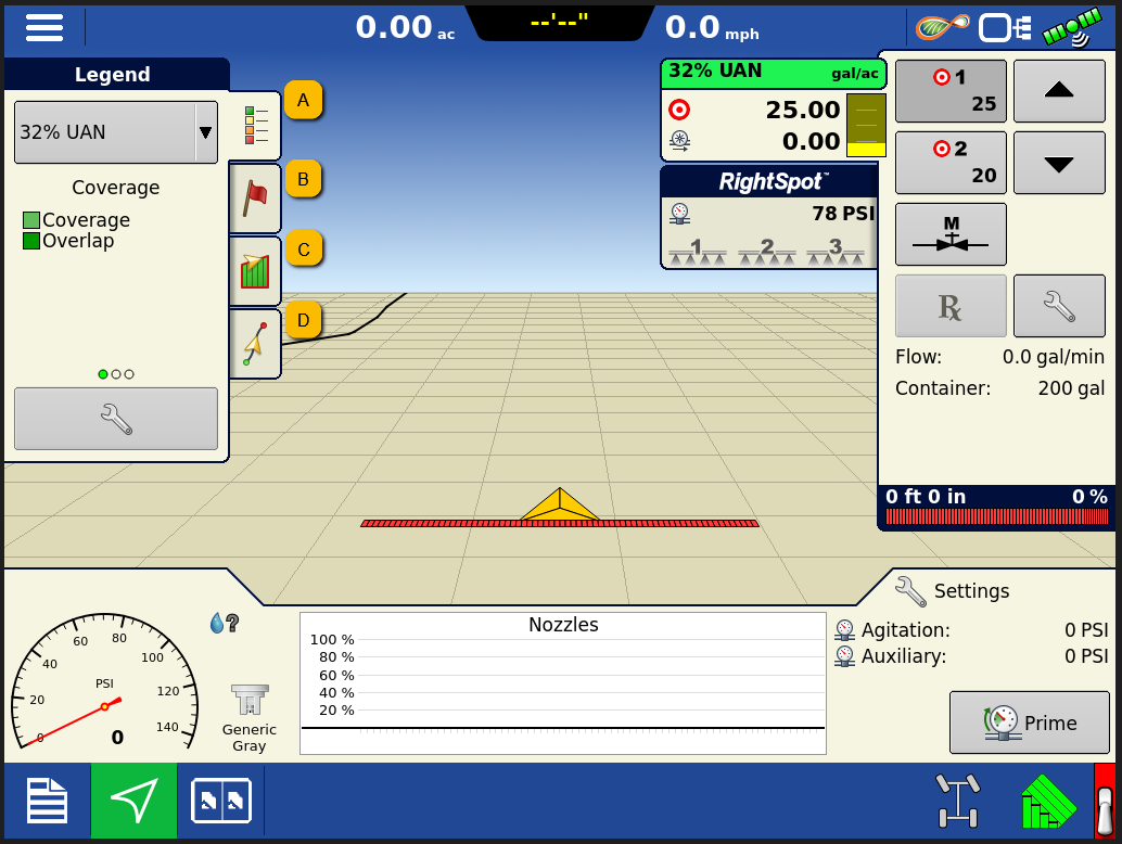
A. Legend Tab
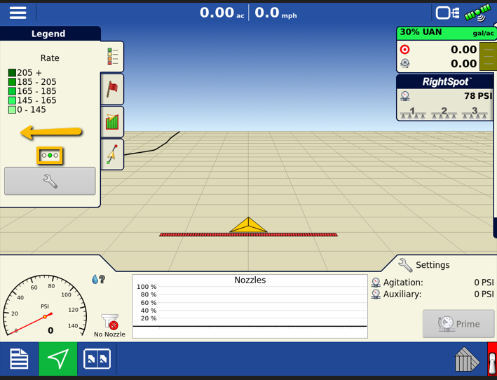
The Legend tab allows you to view the parameters of the colors that are painted.
Changing Attributes
To change the attribute of the map being displayed, swipe right on the legend. The circles near the bottom of this tab will indicate how many different attribute maps your system is recording.
Adjusting Legend Ranges
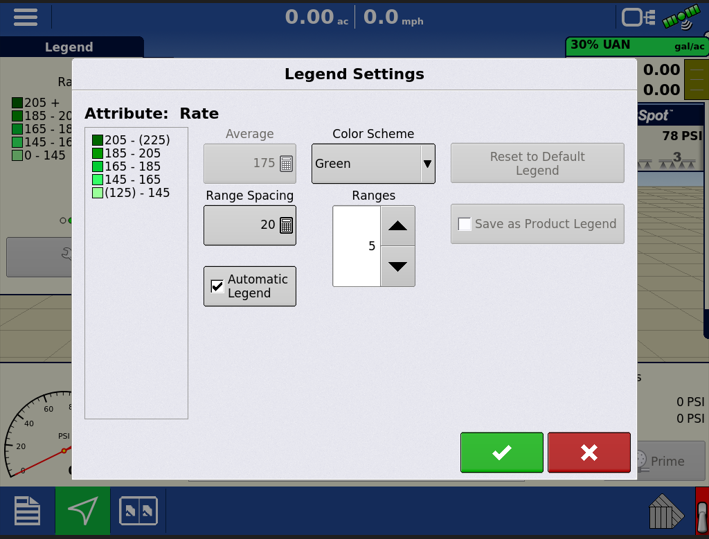
When loading into a run screen, the InCommand will make a default set of ranges based off the product type. These can be adjusted from the run screen. Press anywhere on the legend and the Legend Settings screen appears. Here you can adjust the legend as you see fit. To change the legend average, you will need to uncheck the Automatic Legend setting. Once the legend is set to your preferences, you can check mark the Save as Product Legend, and from then on that legend will always be displayed when the associated product is selected.
Changing Map View
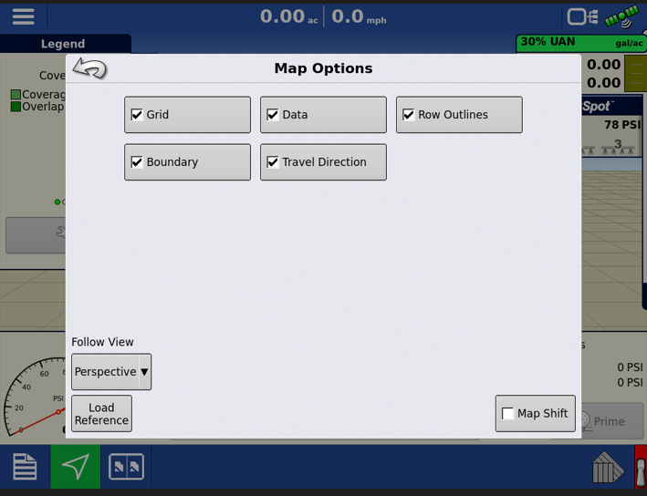
You can adjust how the map appears and what is displayed on the map by the settings in the Map Options Menu. Here, you can modify what is displayed or hidden on the run screen.
Map Shift is used to shift the onscreen map and account for time base inaccuracies with lower accuracy GPS receivers. This is done by doing a quick survey and creating a reference point. Any time the user would like to adjust the map to fix GPS drift inaccuracies, they will go back to the reference point and perform a survey to shift to the current position.
Load Reference button will load any previous as-applied or coverage data in that field, that can be used for AutoSwath™ purposes.
™ 
B. Markers Tab
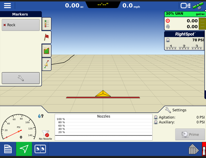
Markers are a collection of point objects that are available on the Map Markers tab of the Mapping toolbox. Map markers allow mapping points on the go in order to identify specific features within a field.
Setting a Marker
To set a marker, navigate to the Markers tab, then press the marker you would like to place. This will then leave a marker in the location you pressed the icon. If the marker you want is not in the list on the Markers tab, you will need to either create it, or load reference marks from a previous event done in the field.
Creating a Marker
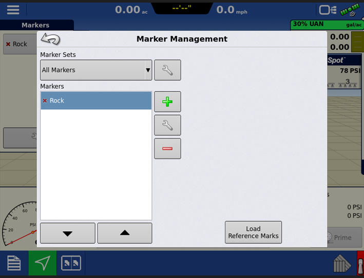
To create a new marker, select the wrench located at the bottom of the Markers Tab. The Marker Management menu will then appear where you can add, edit or delete any markers.
C. Field Tab
Within the fields tab, you can manage your boundaries, headland areas, and even enable topography maps.
Boundary Options
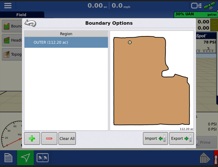
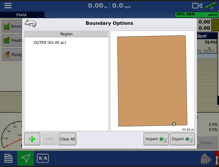
Use the Boundary Options screen to Import Boundaries, Export Boundaries, and Clear All Boundaries.
Creating an Outer/Inner Boundary
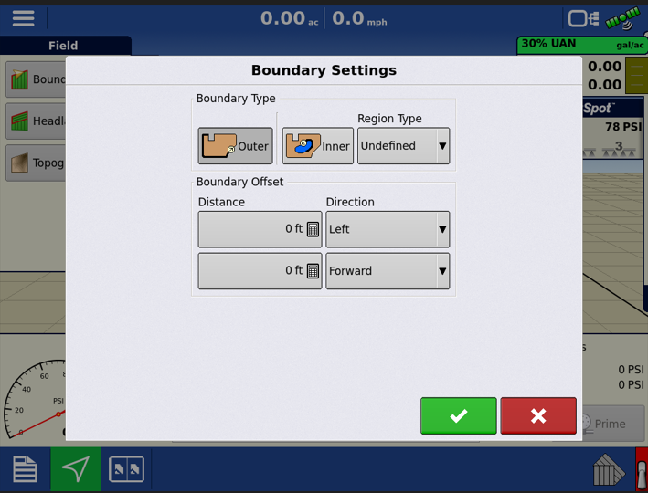
If this menu is empty, this would mean that you do not have a boundary set up for the field selected. If wanting to create a boundary for the field, select the green + sign in the bottom left of the window. The Boundary settings menu will then appear where you will select the boundary type, region type (If it is an inner boundary), and any boundary offsets.
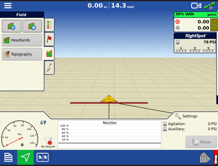
You will then be brought back to the run screen. As you move, you will notice a line trailing the vehicle, which is your boundary line. The other line, trailing at an angle, is the snap line from your starting point. During the creation of a boundary, the Pause/Resume button and stop button appear at the top of the Field tab.
When creating a boundary, use the Pause Boundary button to create a straight line between two points. To do this, drive the vehicle to a point, press the Pause Boundary button, then drive to the second point. Press the Resume Boundary button to create a straight line between the current point and the pause location.
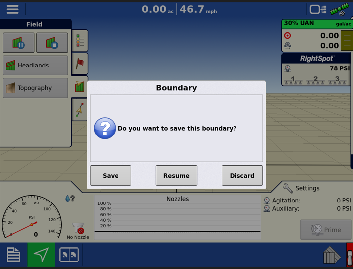
After the boundary is run, press the Stop button to complete the boundary. At the Boundary screen, choose whether to Save, Resume or Discard the boundary.
Once the boundary is saved, it will then appear in your Boundary Options menu.
Headland Options
The Headland Options menu allows you to set up headland recognition for a field. Start by selecting the Headlands button within the Field Tab. Here, we can create, load, edit, and even set alarms for headlands.
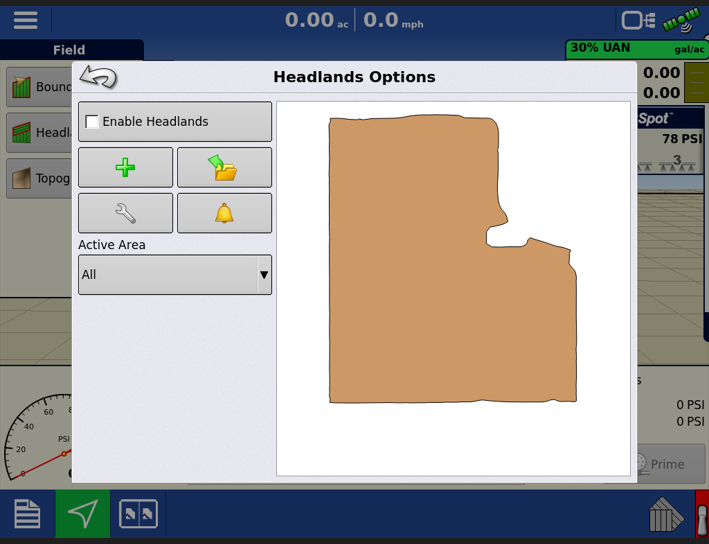
Creating a Headland
To create a headland, start by selecting the green + icon. The Headland Type menu will then appear, asking how you want to define the headland.
All-Around: This option will use the perimeter of the boundary and number of implement widths to calculate headland area from each direction of the field boundary.
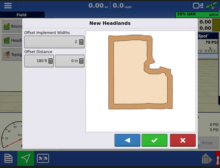
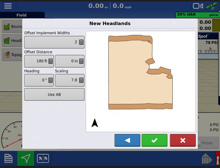
Top-Bottom: This option is like the All-Around option, however it only places the headland area on two sides of the boundary. Use the heading setting to adjust the headland portions of the field (EX: If you wanted the headlands on the East and West, instead of North and South, you would put in a heading of 90 degrees.) You may also add a Scaling Value, which is the variation that is allowed (from perpendicular) to include part of field boundary in the headlands. If unable to get those to match up quite right, you can also choose to Use AB, which will allow you to select a previously made AB line to use for defining the headlands.
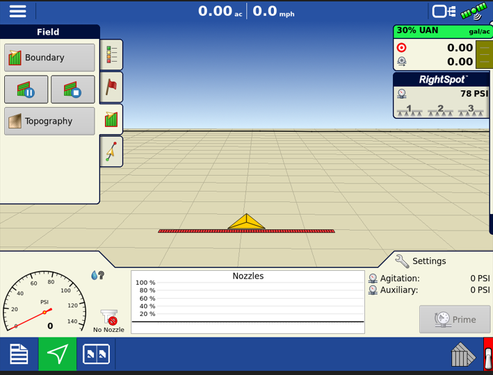
Driven: Driven is much like creating a boundary. With driven selected, it will bring you back to the run screen, where you can then drive the headlands area. The Pause and Stop Icons will appear under the field tab and operate just as they do with boundary creation.
Setting an Active Area
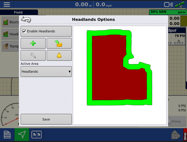
When headlands are enabled, you have the option of choosing what area is the Active Area. If Active Area is set to All, the headlands will be displayed, but it will have no effect on turning the product on/off. With Headlands selected, the product will only be applied to the headland areas (shaded in green.)
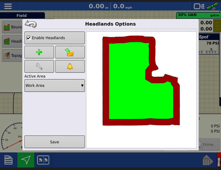
With Work Area selected, this will highlight the inner areas of the field that is not a part of the defined headland. This will stop the application of a product over the headlands.
Topography
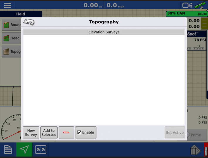
You are allowed to have multiple topographical elevation surveys for the same field. To run a survey, select the New Survey icon within the menu. Once a survey is generated, you can add, delete, or enable/disable the survey. If you have multiple surveys, highlight the one you wish to use, and select Set Active to have it overlay on the run screen.
D. Guidance Tab
Creating a Guidance Line
To create a guidance line, start by selecting New Pattern in the Guidance tab.
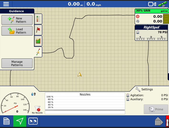
The New Guidance Pattern menu will then appear, where you can select the pattern you wish to use. Different patterns will have different Pattern Options that you can adjust.
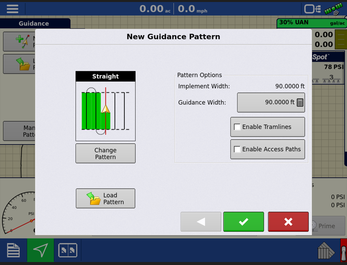
Once the desired pattern and patterned options are entered, you will be brought back to the run screen. The Guidance tab will now show an AB, Heading, and Calculator buttons. The heading icon will display your current heading direction in degrees. If you want to base the AB line off the current heading, select the icon and the AB line will generate. If you would like to manually type in the heading to base your line of off, select the calculator icon and enter the heading. This will then generate the pattern around that heading. If wanting to drive the pattern, start by selecting the AB icon, which will drop your A point. When coming to the end of your pass, you will press the icon again to drop the B point.
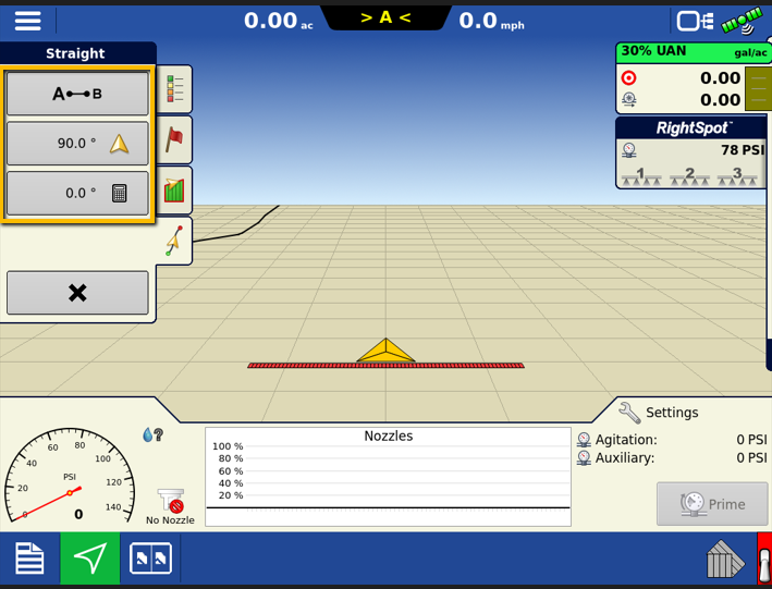
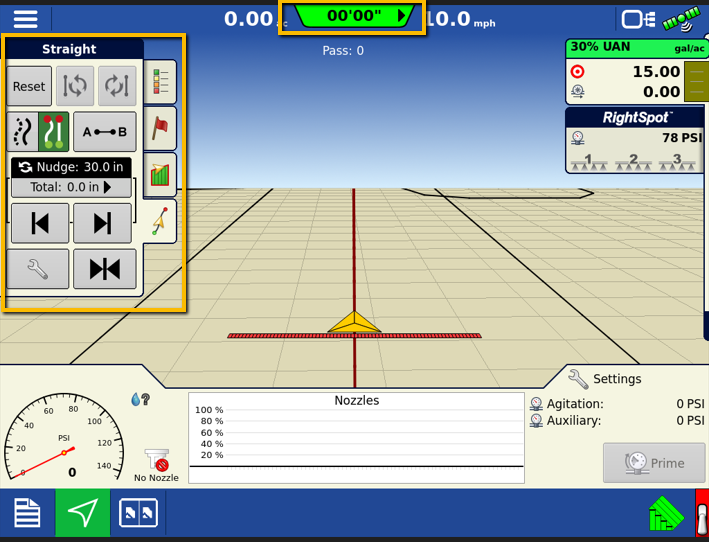
After a Guidance line is set, the guidance tab will display with many more options that you can choose from to adjust the guidance line on the go. Your light bar across the monitor will also become active, and the estimated off-line measurement will be displayed at the top of the screen.